Body
Lift
As
we move forward with the restoration of the 1969 Kabriolet,
we
now encounter the task of removing the body from the chassis.
Prior
to embarking upon the restoration, we decided to have the
chassis pow-
der coated, which necessitates the need for removing the body
from
the chassis.
There
are other needs for body to chassis removal, other than simply
wanting the chassis powder coated as in our case. Replacing
the
heater channels and floor pans are two good examples.
At
first glance, the thought of separating the body from the
chas-
sis seems daunting at best. In all actuality, the process
is quite
simple and can be tackled by the layman and a few willing
partici-
pants. Probably the most difficult part of the job is not
the actual
work in removing and preparing the various components, but
gathering
four strong individuals to lift the body, and having the necessary
space to work with.
The
body is secured to the chassis by a series of bolts, about
34
total. So roll up those sleeves, stock up on elbow grease,
and let's
get started!!
The
first step in the process is to disconnect the negative battery
cable.
Remove
rear seat bottom and backrest section, as well as the two
front seats from vehicle.
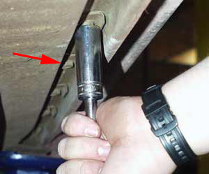
With
the rear seat bottom section removed, and remove the four
17mm
headed bolts that secure the body to the rear cross tube,
and the two
(four 17mm headed bolts for 1959 and earlier Beetles) 17mm
headed
bolts that secure the body to the rear cross members (see
photo).
Sometimes
the carpet that covers the heater channels is cemented onto
floor pan. If the carpet is cemented, pull it free from the
floor.
Open
the engine lid and disconnect the following wires: oil pressure
switch, terminal #15 from the coil, and voltage regulator
(for 1967
and later Beetles, the voltage regulator is located underneath
the
rear seat, on the left side).
Remove
air cleaner from carburetor (not truly necessary, but cuts
down on the height of elevation necessary to remove the body).
Also,
be sure to cover the air intake portion of the carburetor
in an ef-
fort to prevent debris from entering.
Detach
electrical cables from starter motor.
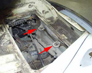
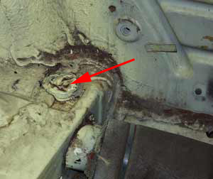
Along
each heater channel, underneath the car, you will find 22
bolts,
11 on each side. Two of the bolts in front have a 17mm head,
while the
remaining 9 have 13mm heads (or 14mm heads for April 1958
Beetles,
chassis # 1904234). Remove all of these bolts and accompanying
plates
(see photo).
Open
the hood and remove the four bolts that secure the fuel tank
to
the body. For cars equipped with a reserve lever, remove this
from
fuel petcock. Elevate fuel tank and crimp fuel line with a
pair of
vice-grip pliers and disconnect cloth fuel line from chassis
fuel line.
With
the fuel tank removed, disconnect the steering shaft from
the
coupler. Disconnect the wires from the brake light switch(es).
For
1965 and earlier standard Beetle models, the brake light switch
wires
must be accessed by removing the cover in the center of the
frame head.
Detach
the hose between the brake fluid reservoir and master cylinder.
Be prepared and have a container to allow the fluid to drain
within.
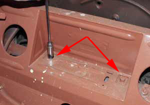
Remove
17mm headed bolts that secure the body to the front axle.
For
1961 and later cars, these bolts are located in the area below
the
fuel tank. For1960 and earlier cars, these are located in
the area
behind the spare tire (see photo).
Disconnect
speedometer cable from left front wheel hub.
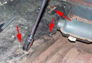
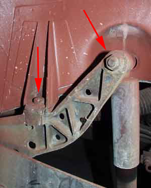
Remove
left rear wheel and remove the 17mm headed bolt securing the
body to shock absorber tower. Reinstall wheel and do the same
for the
right side (see photo).
Remove
choke cable from dashboard for cars equipped with a choke
cable.
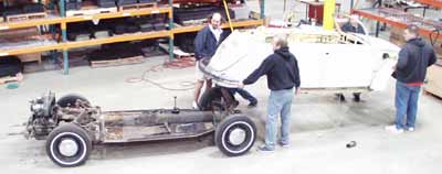
The
body is now essentially ready to be lifted from the chassis.
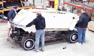
There
are two methods of removing the body from the chassis. The
ideal way is
to lift the body, using four individuals, while a fifth individual
pushes the chassis clear. If no room is present frontward
or rearward,
the body can be lifted and moved to an area beside the chassis.
If the
latter method must by used, USE CAUTION!! Simulate the move
and make
sure everybody involved knows exactly where the body is to
be placed,
as well as any obstacles that they may encounter while moving.
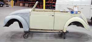
With
regards to convertible models, special care must be observed
prior to removing any body to chassis securing bolts. Convertible
mo-
dels use strengthening rails, which are welded onto the bottom
of the
heater channels to compensate for the lack of a metal roof.
If the
strengthening rails have been weakened by corrosion, you will
need to
brace the doorjambs with a section of wrought iron or heavy
wood.
Otherwise, you risk the chance of having the body literally
folding
in half upon elevating the body from the chassis.
If
braces need to be constructed for convertible models, you
will
first need to establish proper door to body alignment gaps.
These
door gaps should be equal from the topside to the bottom side
of
the door. The door gaps can be adjusted by placing shims between
the
shock towers and or front axle to body mounting locations.
Once es-
tablished, removed the striker plate and door from each side.
Measure
the door opening from the striker plate side of the door,
to the hinge
mounting side of the door. Using a section of wrought iron
(or similar
metal), cut accordingly and weld a metal bracket onto each
end. The end
brackets need to be large enough to accommodate three 6mm
bolts (as to
mount onto the striker plate location of the quarter panel),
and two
8mm bolts (as to mount onto the door hinge side of the body).
With
the proper sized end plates mounted, mark and drill holes
into each
end plate to fasten the brace onto the striker plate and hinge
side
of the body.
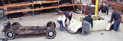
Lift
slowly on the body to ensure that nothing is catching. Areas
for
concern are the engine tin breastplate and steering shaft.
If the
breastplate catches, as in our procedure, simply remove it.
With re-
gards to the steering shaft, it may be best to remove the
steering
shaft from the car.
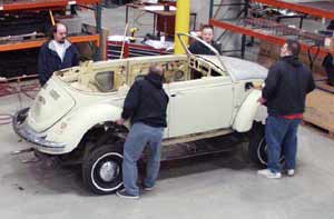
Once
ready, have four individuals grab a fender and heave-ho!!
Installation
is a reversal of the above, with the following points
observed:
Replace the body to chassis pads with fresh units. The body
pads are
located between the body and front axle, body to rear axle
cross
tubes, and shock towers.
Replace the body the chassis seal with a fresh unit. Use a
8mm hollow
punch for the various mounting hole locations, then glue in
place with
weatherstrip adhesive. Nails were originally used to secure
this seal
in place, however weatherstrip adhesive can serve as a water
barrier.
It is also a good idea to apply a silicone based sealant on
top of
this seal for good measure.
To guide the body into place, screw one 8mm stud into each
of the rear
shock tower journals. A 10mm X 75mm or so bolt works well;
simply cut
the hex head from each one to serve as a stud.
After the body is placed onto the chassis, tighten all of
the 17mm
headed bolts first, then the 13mm variety (or 14mm for early
cars).
All chassis to body bolts should be tightened to 11-14 ft.
lbs.