| |
|
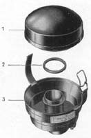
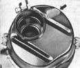
Late'49-Late'53
This
air cleaner is often referred to as the "coffee can"
air cleaner. This style cleaner has 10 holes located on the
left side, which allowed for an intake of air. The inner cylinder
was packed with hair material, which was to be soaked in degreasing
cleaning solvent, dried and moistened with SAE 20 engine oil.
Mann was the manufacturer of this particular filter. Knecht
made another style and was available as an option and intended
for dusty regions. This air cleaner was cylindrical in design,
and had 2 intake slots located in the housing. This air cleaner
is comprised of two halves, which were held together by 2
spring clips. When separated, an internal filter could be
easily cleaned, then
reinstalled. |
 |
Knecht
dusty region air filter
This filter was offered as an option starting in 1950, and
was intended for use in regions with excessive dust. |
 |
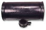
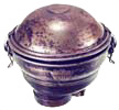
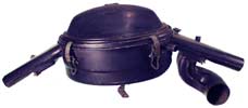
Late'53-Mid'55
This was the start of the oil bath style air
cleaner as standard equipment for VW Beetles. This particular
cleaner was installed intermittently along with the "coffee
can" style filter, starting in late 1953. This air cleaner
featured an upper and lower hemisphere, with the upper hemisphere
being secured to the lower by means of a metal strap. The
lower chamber of the filter was to be filled to an inscribed
mark with SAE 20 engine oil. The upper portion housed a fibrous
material, which was to be soaked in degreasing solvent, dried,
then moistened with SAE 20 engine oil.This was the first oil
bathed filter that was available for VW's. The oil bathed
filter functions by extracting dust and dirt by means of pulling
heavy particles downward within the lower chamber, and trapping
them within a pool of oil. The oil bathed filter also served
as an air intake noise damper. The late'53 strap style air
filters were made with one minor flaw (see lower photo) in
that the upper portion lacked a lip, which allowed moisture
to flow into the lower chamber. The 1954 design included this
lip and thus cured the water infiltration dilemma. This air
cleaner was used intermittently in 1953, thus there is no
chassis number for its birth. However, it was used through
Mid'55, ending with chassis number 1-0869850.
|
 |
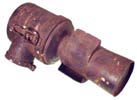
Mid'55-1960
This
oil cleaner is very similar to the former design, with the
strap deleted in lieu of 2 spring clips. Two different manufacturers
produced these filters, Mann and Knecht. Both were similar
in size and shape. The lower chamber of the filter was to
be filled to an inscribed mark with SAE 20 engine oil. The
upper portion housed a fibrous material, which was to be soaked
in degreasing solvent, dried, then moistened with SAE 20 engine
oil. This air cleaner started at chassis number 1-0869851
in 1955. |
 |
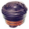
|
This
is another version of the Mid'55-1960 air cleaner. Notice
the size and shape difference as compared to the one above.
|
 |
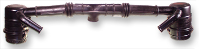
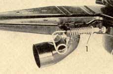
1961-1965
VW
introduced an entirely new air cleaning arrangement starting
with the 1961 model year. It featured a warm air intake hose
and a controllable flap valve. The controllable flap valve,
in the released position at temperatures under 67 degrees
Fahrenheit, is opened by means of an induction of air as the
the engine speed increases. The valve shaft is equipped with
a small weight for compensation purposes. In the fixed position,
at temperatures of 68 degrees Fahrenheit and higher, the air
intake tube is opened and the connection for the pre-heater
pipe from the left heater junction box is closed by the valve
simultaneously. Thus, this clever arrangement supplies warm
air at low engine speeds in an effort to prevent the formation
of ice inside the carburetor, particularly when the weather
is cold, and also helps with fuel
conservation. The upper illustration depicts a 1962-1965 air
cleaner. The 1961 air cleaner does not possess the fitting
for the air breather. The lower photo illustrates the 1964-1965
version of this air cleaner. There is a depression located
on the underside of the lower hemisphere which makes way for
the larger 28 PICT-1 carburetor used on these years.
|
|
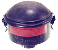
1966
Only
This
air cleaner still has the same function as the 1962-1965 variety,
but much more flat and broad in profile. VW no longer recommends
the cleansing of the upper hemisphere filter element with
degreasing solution, rather it should be scraped clean with
a flat instrument. The oil in the lower chamber should still
be filled to the inscribed line with SAE 20 engine oil. |
 |
1967
Only
This is the debut of the dual intake air snout, dual preheat
oil bath air cleaner. The oil breather fitting was still present
on the oil cooler as in the 1962-1966 years, and was connected
to the oil filler by means of a cloth covered breather hose.
Both intake air snouts possess air control flaps to regulate
preheated air to the carburetor.
|
 |
1968
Only
This oil bath air cleaner, like the 1967 model is fitted with
two air intakes. Both intakes are fitted with air regulating
flaps. Starting with this year the right flap regulates air
intake according to engine temperature. The cold engine draws
air from the cylinder/head area where the engine warmth is
created quickest. This flap is regulated via a cable that
connects to the air flaps at the base of the fan shroud. |
 |
1969-1970
VW eliminated the left air intake. Also incorporated was an
additional flap that controlled the fumes entering from the
crankcase. At higher speeds this flap is opened and fumes
from the crankcase are drawn into the intake system. This
is one example of many pollution controls that VW was implementing
in 1968-1969.
|
 |
1971
only
Starting with engine AE 0 000 001 VW incorporated a separate
thermostat located on the backside of the air filter assembly.
Incorporating a separate thermostat deleted the cable that
tethered the air filter assembly to the engine on prior models
thus allowing for a much simpler/quicker cleansing.
|
 |
1972
only
The flap regulating intake air is now controlled by two factors,
engine load and air temperature being drawn in. This new system
responds quicker to engine operation conditions. Intake manifold
vacuum is routed through a thermostat, mounted to the top
of the air cleaner, into a vacuum servo mounted to the air
intake snout. This servo actuates a flap that controls the
intake of air flow, warm air from the head/cylinder area or
cool air from the engine compartment.
|
 |
1973-1974
and 1973-1979 engines without fuel injection
VW moved from the oil bath filtration system to the newer
paper element style. The housing is now constructed of plastic.
Intake air regulation is controlled using the same methods
described in the 1972 only above.
|
 |
| 1963
is the first year for the accessory dual cyclone air cleaner
arrangement. Cars equipped with dual cyclone air cleaners
should use a carburetor that has the upper vacuum drilling
to the venturi and the power fuel jet blocked. The Bosch VJU
5 BR 8 distributor is used for the dual cyclone air cleaners
as well. The ignition timing point is 12.5 degrees before
TDC. The right hand mark on the crankshaft pulley should be
4mm to the left of the crankcase joint. |
|
|