|
|
|||
| Copyright © Wolfsburg West 2001 |
|
Starter
Circuit Troubleshooting
|
|
| First,
let’s look at the heart of the system,
the starter. Starters are a very misunderstood electrical component. Bosch claims that warranty returns on starters are mistakenly ex- changed in over 50% of the cases. A starter motor is a basic electric motor with a few peculiarities that we should ex- plain. Mounted to the top of the starter motor is a small round cylindrically shaped device known as the solenoid. The solenoid is an electric gadget that engages the sliding gear of the starter into the ring gear of the flywheel, while sup- plying current to the starter motor at a precise moment. As you can see, the solenoid really has two distinct functions, movement of the drive gear into the flywheel and to supply current to the starter motor itself. |
|
| HOW
CURRENT FLOWS THROUGH THE STARTER
CIRCUIT. Voltage from the battery is carried to the ignition switch via a heavy red wire. From the ignition switch, voltage is sent to the starter solenoid. The starter solenoid first moves the starter gear into the flywheel ring gear and secondly applies current from the positive battery cable to the starter motor, thus rotating the flywheel in an effort to start the engine. One important concept to remember is that the ignition switch only supplies current to the solenoid. The solenoid is what does all the work, in terms of switching the starter motor on and off. Starters can demand in excess of 300 amps all of which is controlled through the solenoid. |
|
 |
|
|
Unique
to the VW supplied starter motor
is the way the arm-
INSPECTING
THE STARTING SYSTEM. HOW
ARE THE GROUND STRAPS? CLEAN
ALL ELECTRICAL CONNECTIONS IN THE
STARTER SYSTEM. If
the above does not fix the problem,
the last step involves Quite
often you will go through all of
the above steps, includ- HOW
A HARD START RELAY WORKS |
|
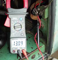
At 12.8 volts a 12-volt battery is fully charged. Static charge is the voltage across the battery with all electrical components turned off. At 13.09 volts, our battery is in tip top shape! |
 |
|
Often overlooked
is the transmission to body ground strap. This electrical |
|
| The positive solenoid wire is easily identified in that it is connected to the solenoid by means of a push-on style connector. | 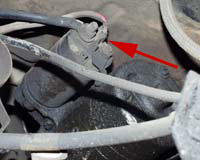 |
|
 |
| Simply take a 6" length of medium gauge wire and strip both ends. Touch one end to the push-on terminal located on the solenoid and the other to the positive battery cable. |
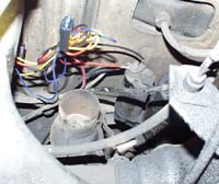
| Here's an example of a car equipped with a hard-start relay. If one is needed for your car, this is the typical mounting position. |
 |
|
|
| The
above illustration demonstrates the routing order of the various wires
that comprise the starter system. This wiring schematic includes the use
of a hard start relay. Please refer to the upper most illustration for
an unmodified version. |