|
Beetle
and Bus American headlight rebuild - Early style
|
|
With
the supply of quality headlight assemblies becoming increasing
difficult to find, we thought this would be a good time
to go over the in's and out's of rebuilding your existing
assemblies.
A
bit of history
Early headlights (1966 and earlier Beetle, and 1967 and
earlier Bus) can be broken down to two different categories.
European and American styles. The European version is easily
identified by the fluted exterior glass lens. This assembly
uses a bulb that resembles an extra large taillight bulb
and relies on the fluted lens to distribute the beam of
light into the correct position.
The American version utilizes an exterior glass lens that
is clear, for the most part. The light bulb in these units
is 7 inches in diameter and commonly referred to as a seal
beam. The sealed beam features a built in fluted surface
that directs the light, which is the reason for the exterior
lens being clear.
Due to the overwhelming demand for the VW, two suppliers
were called upon to adequately supply headlight assemblies,
Hella and Bosch . Both manufacturers got a little creative
with regards to placement of the headlight beam adjustment
screws. These screws are located in the face of the chrome
ring surrounding the glass and are used to adjust the headlight
beam after installation. The position of these screws is
determined when the mounting tab is in the 6 o'clock position.
Through 1960 , Bosch placed their adjustment screws at the
9 o'clock and 12 o'clock position for the Beetle, and 12
o'clock and 3 o'clock for the Bus. Hella units possessed
adjusting screws at the 5 o'clock and 7 o'clock position
for both Beetle and Bus European models through 1960, while
the U.S. Beetles and Buses used the 5 o'clock and 7 o'clock
adjusting screw locations through Mid'1964. Hella and Bosch
finally got on the same page in 1961 as both units featured
adjusting screw holes in the 2 o'clock and 7 o'clock position
for European Beetles and Buses. U.S. cars did not see the
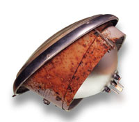
2 o'clock and 7 o'clock position until Mid'1964. Our victim
today will be a 2 o'clock and 7 o'clock bus assembly that
is in need of some serious attention.
|
Removal
and Disassembly
Remove the assembly from the car by unscrewing the large screw
at the base of the assembly. Be careful to have a hand in
place on the lens as loosening this one screw will release
the entire assembly from the car.
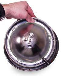
With the headlight assembly removed and sitting on your workbench/table,
remove the sealed beam by removing the wire clips that secure
the sealed beam retainer. The clips are removed by depressing
on the end closest to you. CAUTION! Use caution when removing
the clips and always wear safety glasses.
Next, remove the remaining spring clips that secure the inner
housing to the chrome ring. Doing this will loosen this housing
from the chrome ring and allow for the removal of the glass.
If your assembly has been together for quite some time, applying
a slight amount of pressure against the glass may be necessary
in order to break the seal (and with any luck not the glass).
Remove the glass from the assembly.
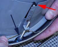
Finish the disassembly by unscrewing the beam adjustment screws
located in the in the face of the assembly. Pay close attention
to the layout of these final components and how they fit together.
|
 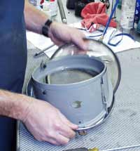 |
| With
the unit fully disassembled remove any corrosion and prepare
the surfaces for a coat of paint. |
 |
Assembly
is fairly simple if you have taken the time to note the correct
location of the components.
In our assembly we are replaced both the chrome ring and the
beam adjusting screws. VW originally used a crimp washer to
hold the adjusting screw snug against the ring. Since crimp
washers are almost never reusable, we suggest using 4 mm nuts
locked against each other(blue arrow). For extra added security,
thread locking compound will help hold the nuts firmly fastened.
|
 |
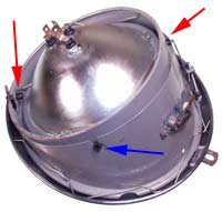
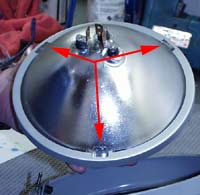
Next,
mount the rubber plugs that the screw lugs affix onto. Note
that there are two different styles, stepped and non-stepped.
The stepped version is designed to accept a spiked lug screw
(red arrows in photo to the right).The non-stepped version
resembles vacuum hose in that it is hollow (blue arrow in
photo to the right). With these two pieces assembled and the
rubber plugs in place, install the spiked screw lug.
Screw the chrome ring to the housing assembly so that the
screws protrude no more than 10 mm through the spiked lug
nut.
|
 |
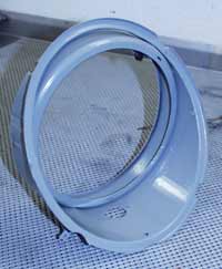
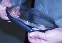
Stretch
the glass lens seal onto the lens making sure that the smooth
side faces the glass lens and the ribbed side faces outward.
Install the lens into the assembly between the chrome ring
and the housing making sure that the center of the lens is
centered in the chrome headlight ring mount tab.
With the housing/glass lens/chrome ring positioned, secure
the assembly by installing the spring clips into the ring.
Remember to wear your safety glasses.
With the assembly back together use some glass cleaner to
cleanse the inside surface of the lens prior to installing
the sealed beam.
|
|
Correct
positioning of the sealed beam is accomplished by lining up
the lugs with the sealed beam retainer ring. The ring is keyed
to fit correctly one way, thus directing the light beam correctly.
|
 |
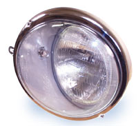
Our
finished assembly.
Headlight adjustment is detailed in a previous tech tip that
you can find by clicking on this sentence. |
 |